Joule Effect
The Joule effect is a physical phenomenon expressing the relationship between the heat generated and the current flowing in a conductor. The equation is as follows: for a current I (Amperes), flowing through a conductor of resistance R(ohm), during t secs: H = I2 R t (in Joules)
A few terminal equipments such as heaters benefit from the Joule Effect. But most of the time, this effect results in unwelcome losses in the circuit, particularly in the distribution cables.
In such cases, we try to reduce the losses by reducing the resistance:
- Low resistivity materials such as aluminum or copper
- Higher section
- Lower length
The design of an installation to prevent power loss is done via norms (NFC 15-100) with maximum voltage drop, depending on the usage and the configuration. Example: max 5% voltage drop for power terminal such as motors, in a public grid, or 6% for lightings, in a private grid. The voltage drop is assessed with very popular tools such as CANECO.
Why care?
All electrical cables have electrical resistance. As current passes through a cable, a small amount of power is lost between one end of the cable and the other, in the form of heat.
Since the usage pattern of our clients in only hypothetical at the design phase, we end up designing for the maximum usage scenario. And there are no good practices that apply ordinarily to reduce the joule effect.
Orders of magnitude
In one of our office installations (a classical medium low voltage installation), the joule effect losses are seen in the transformer and in the cables. The losses are distributed almost equally in the transformer as well as in the cables.

The losses in different cables installed by us are as follows:
♦ In cables supplying power to terminal equipments

As can be seen from the table above, the joule effect losses are variable as they are dependent on many factors. On an average, they are higher in single phase cables than tri phase cables.
♦ In cables supplying power to Electric cabinets:

As can be seen from the table above, the cables supplying power to electrical panels are larger in diameter than the cables supplying power to terminal equipments. This helps to minimize the voltage drop (and hence the losses) in the cables to the panels thus allowing enough margin for dimensioning in the cable connecting terminal equipements.
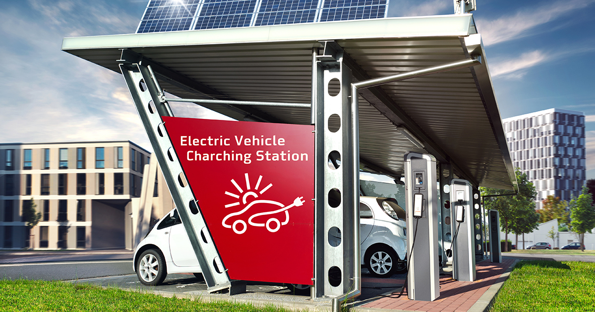
Achieving zero losses are not possible but reducing these losses even further should be our goal. Especially for equipments consuming high amounts of energy like chillers and electric vehicle charging points, we must give attention to the dimensioning of cables as our clients are not aware of the inevitable losses already integrated into our installation.
How to reduce electrical energy losses in electrical installations?
To give you an example, let us consider the schema of electric vehicle charging points. This consists of a single depart of Al core 4×70 cable of length 100ml from TGBT to TD, and then 10 segments of 3G25 cables of 20ml length each. For Usage factor (over 24 hours) = 30%, Simultaneity factor (simultaneous charging) = 85% and Load factor (% of max. power drawn) = 100%, losses are calculated for 10years. The charging box in consideration is Schneider 7,4kW EV link Wall box.
Scenario 1: Increasing the diameter to reduce the resistance of the cable.

As seen above, this can result in reduced losses by reducing the current flowing in the cable, but the losses can be marginal for justifying the increase in cost of installing higher section cables. Given the fact that the cost of cables does not necessarily increase a lot from one diameter to another (for example, the selling price for 4×70 cables is 14.91€/ml while the selling price for 4×95 is 17.79€/ml – a difference of less than 300€ for 100ml of this cable), the current pricing for different diameters must be considered before taking a decision.
Also, to be considered is the addition of materials (notably Aluminum) that will result in added encapsulated lifetime carbon emissions of around 200kgs CO2eq.
Scenario 2: Not using all the charging points at the same time while increasing their rate of usage.
This has an interest not only for reducing the power subscribed but also to reduce the joule effect losses in the circuit. The table below shows how reducing the power used at the same time and using the charging points longer can reduce the joule effect losses in the cable connecting the general low voltage panel and the panel for electric vehicles.

For a given energy, with a lower coefficient of simultaneity, the power drawn at any point of time is reduced, thereby reducing the losses in the cable delivering power to the panel over a long period of 30 years.
This can be done by one or a combination of the two following methods:
♦ Communication between chargers:
Today, the terminals communicate, via a standardized radio protocol (wireless) called OCPP which makes it possible to visualize the occupation of the terminals, the load taken by the terminal. Using this protocol can help us to prevent overloading of terminals at a given hour.
♦ Energy management of terminals:
Dynamic energy management, interfaced with the building, is done via an energy terminal, in particular that of Schneider Electric (EVLINK LMS) or Park n ‘plug.
This dynamic management system may cost around 6000€ for 20 charging points. Over a 30-year period, the part of the benefit from the reduction in joule effect losses may be 20 MWh (from the table above), i.e., 1500€ to go along with the benefits from the reduction in subscription of electricity with the electricity provider. Other benefits include conforming to fire safety regulations at the parking level. And, for a given amount of power, this method enables us to install a large number of chargers without modifying the transformer or the general low voltage panel. However, the service might be ‘delayed’ for some clients.
Conclusion
Joule effect losses in cables are inevitable. The joule effect is limited to less than 2% for all the segments in our installation. We can try to reduce this even further by targeting the high-power consuming cable sections in our installation.
Did you like the article ?